
Electromagnetic weaponry for fun and profit
2019-10-29
Anyone who has played Halo and fired the Gauss cannon on the Warthog has experienced a strong desire to do it in real life. Usually this is cut down by the idea that Gauss guns aren't real. But of course, they are, and I've built a few. Feel free to replace all mentions of "coilgun" with "Gauss superaccelerator" or "magnetic spaceship cannon" if this will satisfy a childhood fantasy of yours.
There are two main types of coilgun I've built:
The "standard" kind, which involves turning an electromagnet on, attracting a ferromagnetic projectile down a barrel towards the coil, then turning the magnet off once it reaches the centre of the coil. This is a reluctance coilgun.
The other kind, which involves turning an electromagnet on and using the sudden change in magnetic field to induce eddy currents in a non-ferromagnetic projectile. The projectile must be an inductor of some kind (e.g. a shorted coil) so that the eddy currents form a magnetic field that repels the projectile away from the coil. This is an inductance coilgun.
I thought an induction coilgun would be easier to time, since we don't have to quickly turn off the coil, but intractable problems led me to turn my coilgun into a reluctance coilgun.
Why not a railgun?
I actually am trying to build a railgun, but it is extremely obvious to me why coilguns are more popular among hobbyists: you don't need moving contacts for a coilgun! It's that simple!
Inductance or reluctance, a coilgun is not a railgun and doesn't require any electrical contact between the projectile and the coil.
What do I need to build it myself?
The bill of materials for a minimal version of this project is actually quite...minimal. My very first coilgun was a low voltage (30V) design, built with parts I had on hand. The voltage had to be low because I had not yet acquired any high voltage diodes or capacitors. All I had was:
Thyristors salvaged from a power drill battery charger (BT151-500R) - decent voltage capability but disappointingly low non-repetitive on-state current capability. This is not strictly necessary for a minimal design, so I won't use it right now.
Some enamelled magnet wire from a transformer from an old computer power supply.
Some 200V 680uF capacitors from the same power supply. That voltage tolerance is weird because it's below what would come from the mains but really high for a "low voltage" project. Nothing special about the capacitance, it was just what I had.
A 120W halogen lightbulb for current limiting.
Various light switches and wiring for the SPDT and DPDT switches you will see later on.
PVC pipe. Get pipe as thin as possible, you want the projectile to be light and fill the barrel, which is much easier if the barrel is smaller. The fact that it doesn't conduct is important to avoid eddy currents (see Lenz's law).
My first Gauss rifle had this design:
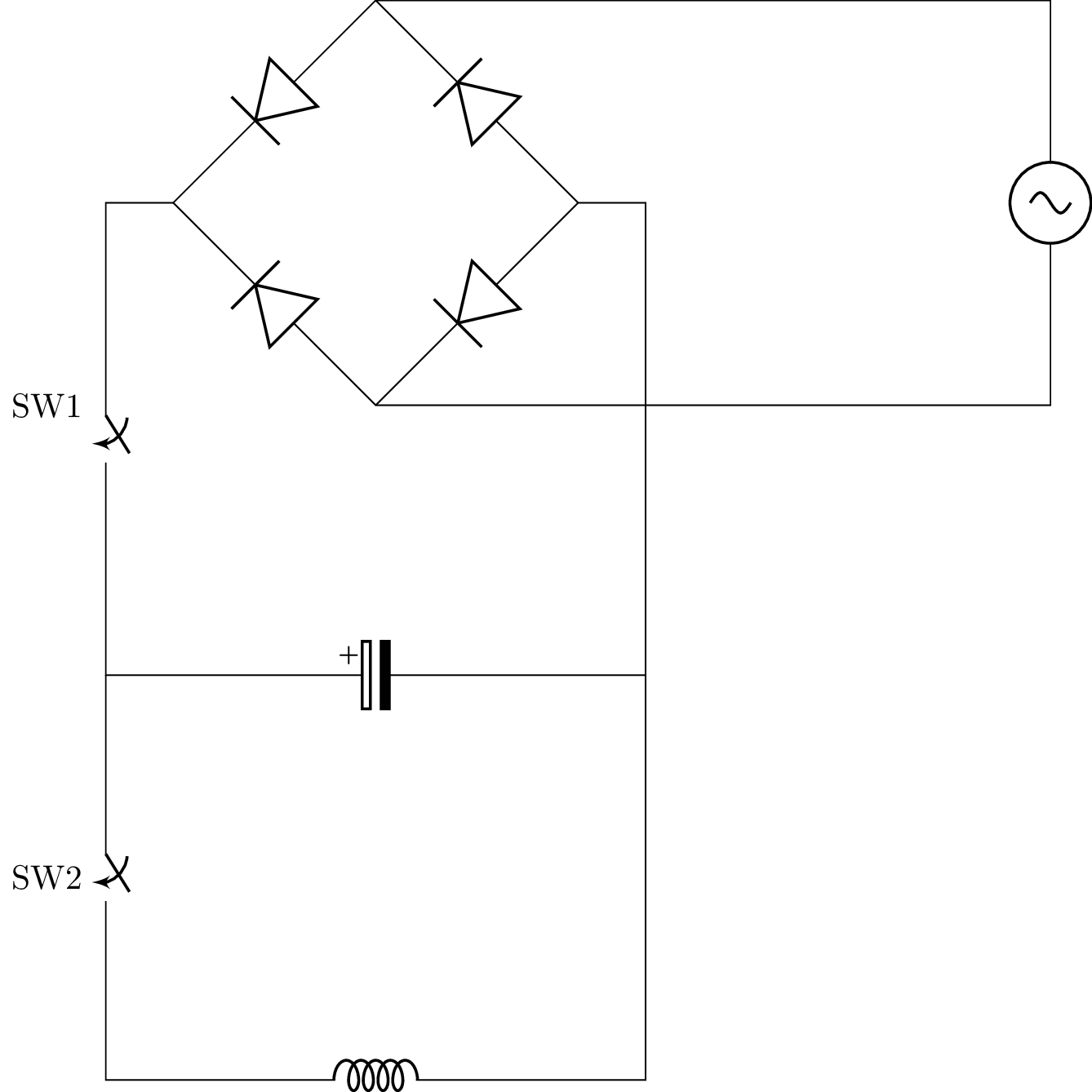
The idea is that all switches are open to start off. Then you close SW1 to charge the capacitor, open SW1 and close SW2 to discharge. There is no timing or triggering circuitry involved, we rely on the capacitor current petering out by the time our projectile passes the coil (for a reluctance launcher) or we just don't care at all (for an inductance launcher).
On a practical level, you wrap the coil around the pipe, put the projectile somewhere in it, and experiment with different capacitances and projectile starting positions until you get something that works as well as possible. I did mention that I started out only using 30V, so you get a stored energy (with two capacitors in parallel) of:
$$E = \frac12 C V2 = \frac12 (1360 \mu \text{F}) (30 \text{V})2 = 0.612 \text{ joules}$$
Is that a lot? Who knows? At 100% efficiency (completely preposterous), this would propel a 1 gram iron nail to:
$$v = \sqrt{\frac{2E}{m}} = \sqrt{\frac{2(0.612 \text{J})}{1 \text{ gram}}} = 35 \text{ms}^{-1}$$
Pretty decent, right? Wrong! So many things were wrong with this initial design it's incredible. Here's a rundown so you don't have to repeat my mistakes.
Efficiency? What's that?
Hobbyist coilguns peak in efficiency at about 1%. Even really good hobbyists can only squeeze out a few percent with really well-designed, multi-stage, low-friction, narrow barrel designs. Those of us building with random pipes and scavenged components can only hope for fractions of a percent.
The solution is to get bigger caps: higher voltages and capacitances. Voltage is more important since it's the highest order term in the equation. Too much capacitance isn't desirable since this increases the time constant $RC$ of the circuit and will lead to slower discharge.
Safety? Never heard of it!
If you accidentally close both switches, you blow the fuse in your plug or, if you're unlucky, you trip your house's circuit breaker and all of the lights shut off. Very dramatic and easily avoided if you wire your switches differently or add some current limiting (in the form of a bulb).
Back EMF
As I learnt (explosively), when you shut off current to an inductor (e.g. by opening a switch), there is a large back EMF. Essentially, a large voltage is induced in the reverse direction, damaging/destroying any polarised components, like that electrolytic capacitor.
The reason for this is apparent if you look at the inductor equation:
$$V = L \frac{dI}{dt}$$
If you cut off the current suddenly, the rate of change is negative infinity, and so is the voltage over the inductor. In the real world, you don't really get an infinite back EMF, but it'll be more than enough to fry your caps.
How does the current traverse the gap when you open your switch? The inductor always wins and closes the gap with an arc, probably damaging your switch too.
The solution is to add a flyback diode, this is a diode connected in reverse parallel with the inductor, so the back EMF is conducted through it and dissipates the energy stored in the inductor safely. Diagrams will come later to make this clearer.
A better design
Some lessons learnt:
- Bigger caps
- Bigger voltages
- Bigger currents
- ...and also more safety I guess
Sounds good. Here's what I did to apply these lessons:
Take apart some servers to get some better caps. I managed to find some 450V 470uF caps like this, good enough to charge directly from the mains.
Replace SW2 with a high-current thyristor, so we can fire the gun many times without needing to replace the switch. I ended up choosing the TYN640RG which can handle 640V (more than enough) and a peak current of ~500A, which should be fine.
Add a current-limiting lightbulb so even if the thyristor and switch fail closed, it just safely turns on the lightbulb. I just found a 120W 240V halogen bulb in a drawer.
Add a flyback diode! I bought a reel of 1N5408G rectifying diodes that can block 1000V and have a fairly small (1.1V) forward voltage. They can also handle fairly large currents.
Here's what my final single-stage design looks like in circuit form:
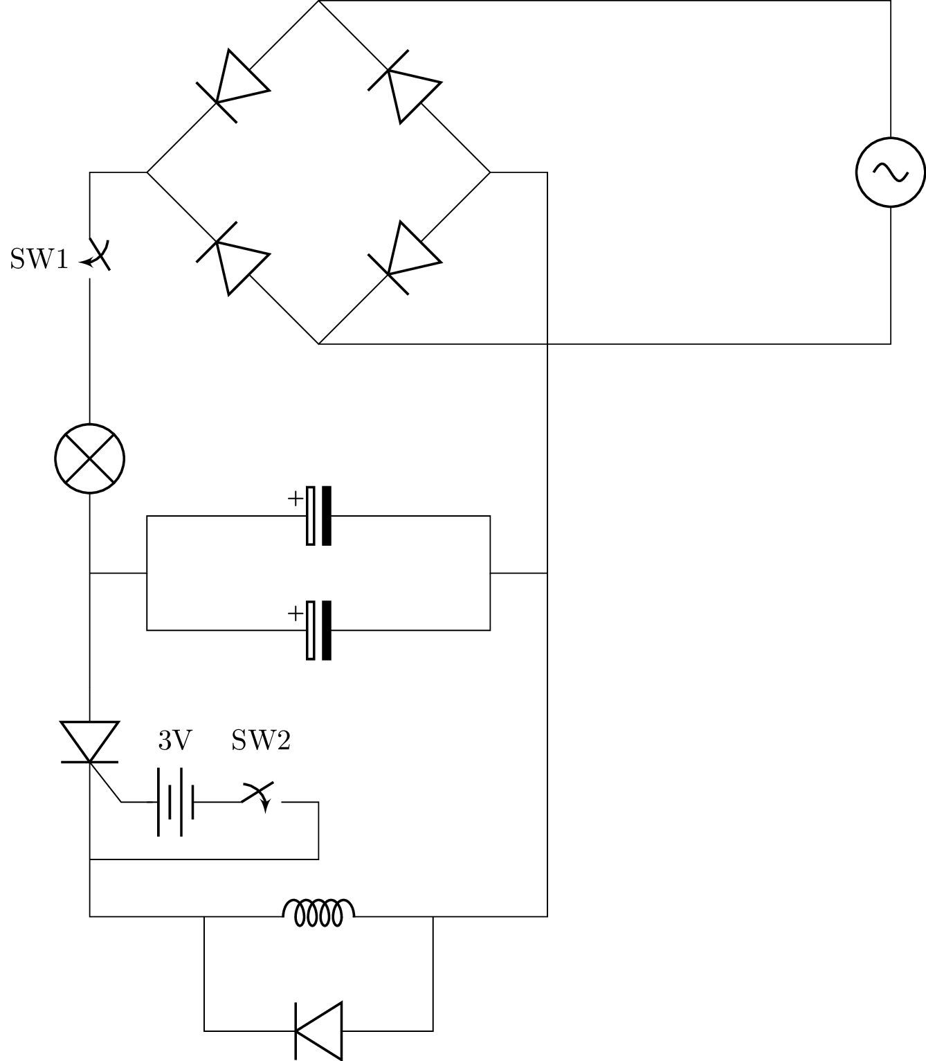
The idea of the circuit is the same, close SW1 to charge, open it, then close SW2 to fire. The difference is that now, if you forget and close everything, the lightbulb just turns on and everything remains safe.
It goes without saying that you should use a ton of wire, otherwise this will draw a huge current and destroy your thyristor. You could also add a tiny resistor if you feel like it, but beware of a high time constant slowing down your projectile, don't make R too large.
Where to now?
I would do some calculations and measurements to work out how good my coilgun is, but there's no point: I already know the path to higher efficiency is having more stages. And bigger voltages will mean faster speeds and maybe something worth making a video about.
I'll also have learnt something about how to make a practical high-speed switching circuit with a photodiode, IR LED and maybe IGBTs instead of SCRs (thyristors), since IGBTs can be turned off.
Or maybe I'll make an induction ring launcher or something.